A fiber link can look perfect from the outside and still become the source of intermittent network faults, poor performance, or unexpected downtime. The difference often comes down to the quality of the joint. Fiber splicing is the process of permanently joining two optical fibers so data can travel across the connection with minimal signal loss. For businesses that depend on cloud applications, IP telephony, CCTV, Wi-Fi, access control, and inter-site connectivity, that detail has a direct operational impact.
Fiber is designed to carry large amounts of data over long distances, but it is not forgiving of poor installation. A contaminated end face, inaccurate fiber alignment, weak splice protection, or incomplete testing can create problems that remain hidden until network demand rises or a link is disturbed during maintenance. Proper planning and disciplined workmanship help prevent these issues before they affect users.
Why Fiber Splicing Matters to Business Infrastructure
A fiber optic cable is often the backbone of a business environment. It may connect a main communications room to floor distributors, link buildings across a campus, provide uplinks for wireless access points, or support cameras and security systems across a large site. When that backbone is unreliable, individual systems can appear to fail even when the devices themselves are working correctly.
The objective of a splice is not merely to connect two fibers. It is to preserve the optical path. Each splice introduces a small amount of insertion loss, meaning a small reduction in transmitted light. In a correctly completed installation, the loss is low enough to remain within the network’s power budget and support stable performance over the life of the cabling system.
This is especially relevant during office relocations, renovations, expansions, and data room upgrades. Fiber routes may need to be extended, repaired, re-terminated, or redirected around new building layouts. Treating these changes as a basic cable task can create expensive rework later. A properly engineered approach considers the required network speed, distance, fiber type, available pathways, future capacity, and the systems that rely on the link.
Fusion vs. Mechanical Fiber Splicing
There are two primary ways to splice optical fiber: fusion splicing and mechanical splicing. The appropriate method depends on the application, performance requirement, project timeline, and budget.
Fusion splicing
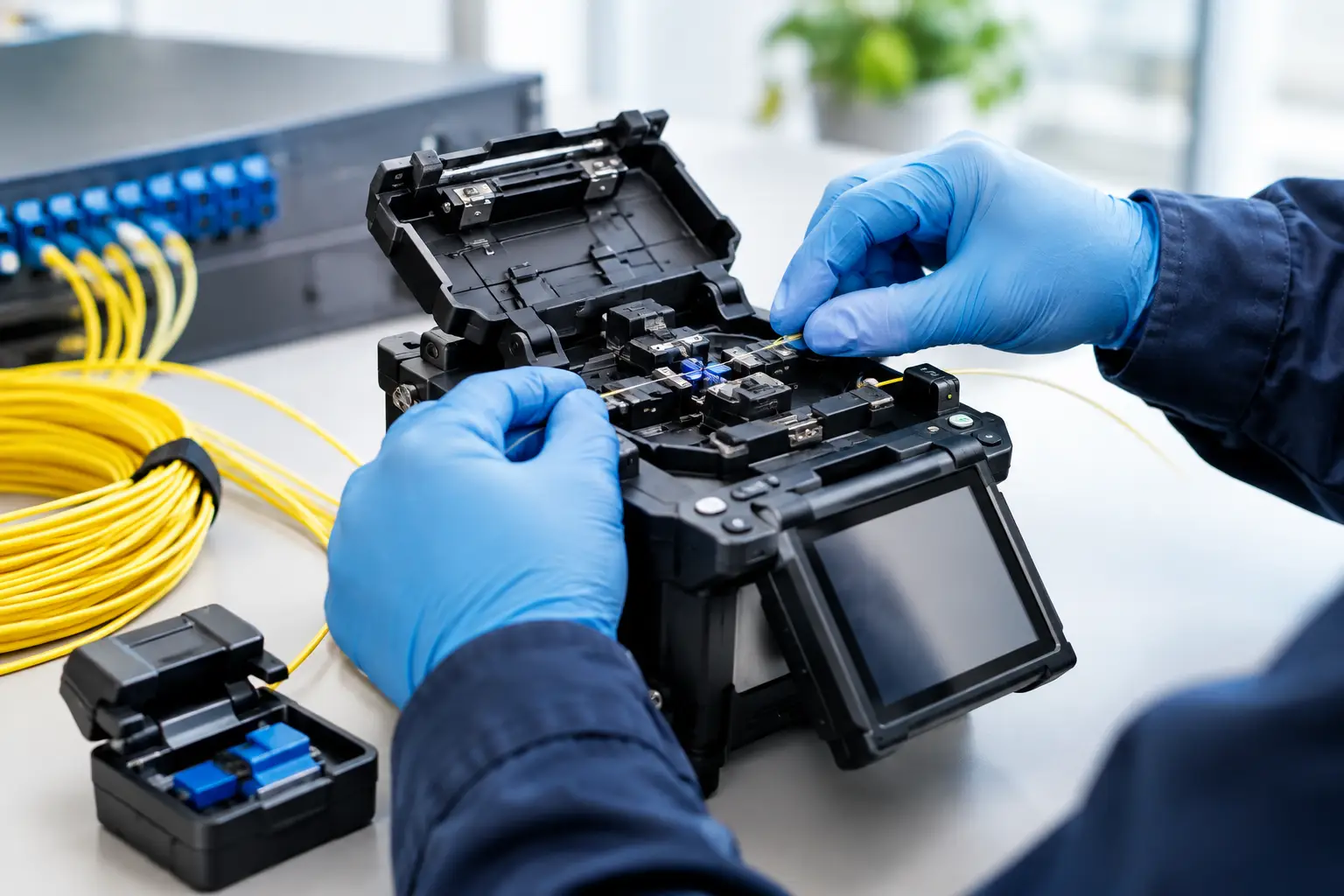
Fusion splicing uses a precision machine to align two prepared fiber ends and join them with an electric arc. The result is a permanent connection with very low loss and low reflectance. It is generally the preferred method for enterprise backbones, long cable runs, outdoor fiber, and high-capacity links where reliability is a priority.
The process requires clean preparation, accurate cleaving, calibrated equipment, and trained technicians. When these controls are in place, fusion splicing delivers dependable performance and strong long-term durability. It is often the right choice when access to the cable is difficult after installation, such as in risers, ceilings, underground routes, or external pathways.
Mechanical splicing
Mechanical splicing aligns fibers using a small device or sleeve rather than permanently fusing them together. It can be useful for temporary restoration work, quick repairs, and certain lower-demand applications. However, it typically has higher loss and reflectance than a fusion splice, and its long-term environmental stability may be less favorable.
Mechanical splicing is not inherently poor workmanship. It has a place when speed or access constraints matter. For a core business connection, however, the lower loss and longer service life of fusion splicing usually justify the additional installation effort.
What a Quality Fiber Splicing Process Includes
Reliable results come from a controlled process, not simply from operating a splicing machine. Before any work begins, the installation team should confirm cable type, fiber count, route condition, termination points, and the network requirement. Single-mode and multimode fiber have different use cases and performance characteristics, while indoor, outdoor, armored, and loose-tube cables require different handling methods.
The fiber must then be carefully stripped, cleaned, and cleaved. Cleaning is critical because microscopic dust, gel residue, or moisture can interfere with alignment and increase loss. The cleaver must produce a clean, flat fiber end. A poor cleave cannot be fully corrected by the splicer.
After the fibers are aligned and fused, the splice is protected with a heat-shrink sleeve and placed in a splice tray. The tray organizes the fibers, protects bend radius, and ensures that future technicians can identify and work on the cable without disturbing adjacent connections. Good cable management is not cosmetic. It reduces the risk of accidental damage and shortens troubleshooting time.
Documentation completes the work. Splice records, fiber numbering, route details, test results, and updated diagrams provide a practical reference for moves, additions, repairs, and audits. In a multi-site organization, clear documentation can save substantial time when an incident requires remote coordination between facilities, IT teams, and service providers.
Testing Proves the Link Is Ready
A splice that looks acceptable is not necessarily a splice that performs within specification. Testing verifies that the installed link can support its intended application.
A light source and power meter can measure overall end-to-end loss. This is useful for confirming whether the completed channel remains within its planned power budget. An optical time-domain reflectometer, commonly called an OTDR, provides more detailed visibility by identifying the location and estimated loss of splice points, connectors, bends, and faults along the cable route.
The right test method depends on the job. A short in-building link may require certification measurements and documented loss results. A campus connection or outdoor route may benefit from OTDR traces taken from both directions, particularly where multiple splices are involved. Testing from both ends helps account for variations that can mask a higher-loss splice in one direction.
For business decision-makers, the key requirement is straightforward: request measurable acceptance criteria and documented results. This shifts the conversation from “the fiber is connected” to “the fiber has been verified for the required service.”
Common Causes of Fiber Link Problems
Many fiber issues originate during installation but appear later as intermittent or difficult-to-diagnose failures. Excessive bend radius is a frequent example. Fiber cables can be damaged or lose signal when pulled too tightly around corners, compressed in crowded pathways, or bent sharply inside cabinets.
Contamination is another common issue. Dust on a connector or fiber end face can cause loss and reflection, even when the cable and splice are otherwise in good condition. This is why inspection and cleaning procedures should be followed whenever connectors are installed, tested, or reconnected.
Poor labeling also creates avoidable operational risk. When patch panels, splice trays, and cables are not clearly identified, routine changes take longer and the chance of disconnecting the wrong service increases. In environments supporting surveillance, door access, point-of-sale systems, or critical communications, a labeling error can become a business disruption.
Finally, capacity planning matters. A link that supports current traffic may not be suitable for future higher-speed applications. Installing adequate fiber counts, selecting the correct cable type, and allowing space in pathways and racks are practical ways to avoid premature replacement.
Choosing a Partner for Fiber Work
Fiber installation is most effective when it is coordinated with the wider infrastructure plan. The cabling route, equipment room layout, network switches, wireless design, security devices, and power requirements should not be treated as unrelated projects. They share pathways, cabinets, maintenance windows, and business continuity requirements.
A capable implementation partner should assess the site before recommending a solution, explain the trade-offs between repair and replacement, use appropriate test equipment, and provide usable handover documentation. Experience with both physical infrastructure and active networking is valuable because it helps identify issues at the boundary between cabling and equipment configuration.
I-Weblogic approaches fiber projects as part of the wider business system, whether the work supports an office move, a growing campus, a retail rollout, or a security upgrade. This coordinated view helps reduce contractor overlap and keeps the infrastructure aligned with day-to-day operational needs.
A well-executed fiber connection rarely draws attention after deployment, and that is the point. When the cabling, splices, testing, and records are handled correctly, teams can focus on serving customers and running the business rather than tracing an avoidable network fault.